The Autodesk Certified Professional in Revit for Electrical Design (RVT_ELEC_01101)
Passing Autodesk Autodesk Certified Professional exam ensures for the successful candidate a powerful array of professional and personal benefits. The first and the foremost benefit comes with a global recognition that validates your knowledge and skills, making possible your entry into any organization of your choice.


RVT_ELEC_01101 Exam Dumps
- Exam Code: RVT_ELEC_01101
- Vendor: Autodesk
- Certifications: Autodesk Certified Professional
- Exam Name: Autodesk Certified Professional in Revit for Electrical Design
Why CertAchieve is Better than Standard RVT_ELEC_01101 Dumps
In 2026, Autodesk uses variable topologies. Basic dumps will fail you.
| Quality Standard | Generic Dump Sites | CertAchieve Premium Prep |
|---|---|---|
| Technical Explanation | None (Answer Key Only) | Step-by-Step Expert Rationales |
| Syllabus Coverage | Often Outdated (v1.0) | 2026 Updated (Latest Syllabus) |
| Scenario Mastery | Blind Memorization | Conceptual Logic & Troubleshooting |
| Instructor Access | No Post-Sale Support | 24/7 Professional Help |
Customers Passed Exams
10
Success backed by proven exam prep tools
Questions Came Word for Word
94%
Real exam match rate reported by verified users
Average Score in Real Testing Centre
87%
Consistently high performance across certifications
Study Time Saved With CertAchieve
60%
Efficient prep that reduces study hours significantly
Coverage of Official Autodesk RVT_ELEC_01101 Exam Domains
Our curriculum is meticulously mapped to the Autodesk official blueprint.
Electrical Systems Modeling & Circuiting (30%)
Master modeling workflows for electrical equipment, lighting fixtures, devices, panelboards, and containment paths (conduits and cable trays). Configure wiring types, system settings, load classifications, voltage definitions, and map dynamic distribution systems.
Electrical Component & Family Editing (25%)
Deep dive into Basic Family Creation and component editing. Master modifying electrical connectors (power, data, telephone, fire alarm), assigning accurate light source properties, building custom annotation symbology, and managing family content behaviors.
View Manipulation, System Browser & Worksharing (22%)
Configure specific electrical view behaviors, parameters, overrides, and view templates. Leverage the System Browser to audit unassigned components, balance circuit loads, and manage collaborative project synchronization through worksets and central model worksharing.
Data Leveraging, Schedules, & Documentation (28%)
Extract and manipulate rich Revit BIM data using project, shared, and global parameters. Create and format panel schedules, lighting loads tables, and material takeoffs. Master automated circuit tagging, wire annotations, and documentation sheet management.
Autodesk RVT_ELEC_01101 Exam Domains Q&A
Certified instructors verify every question for 100% accuracy, providing detailed, step-by-step explanations for each.
Question 1
Autodesk RVT_ELEC_01101
QUESTION DESCRIPTION:
How can an arrowhead be added to a lag leader line?
Correct Answer & Rationale:
Answer: C
Explanation:
In Autodesk Revit for Electrical Design , arrowheads on leader lines—such as those used with tags, text notes, or annotations—are controlled through Type Properties , not through instance properties or free-end options.
According to the Revit MEP User’s Guide – Annotating Chapter (Chapter 47 and 42), the section “Modifying Tags” explains:
“Select the tag, and on the Properties palette, click (Edit Type). In the Type Properties dialog, select a value for Leader Arrowhead to add an arrowhead to the leader line.”
This confirms that the arrowhead is defined at the type level , meaning any change applies to all tags or text notes of that annotation type throughout the project. The Leader Arrowhead property allows the designer to choose from predefined arrowhead styles (like “Filled Arrow,” “Dot,” “Tick Mark,” etc.), which are defined globally under:
Manage tab → Settings panel → Additional Settings → Arrowheads.
Furthermore, the document specifies under “Leader Arrowhead Properties”:
“Sets the arrowhead shape on the leader line. The value is the name of the arrowhead style defined by the Arrowheads tool.”
This behavior applies to all annotation categories, including text notes, keynotes, material tags, and electrical device tags, maintaining consistency across all view types in an electrical project.
Therefore, Option C is the correct answer because arrowheads are configured via Type Properties , while the other options are inaccurate:
Option A (Free End) only defines leader attachment behavior.
Option B (Instance properties) does not include a “Leader Arrowhead” toggle.
Option D (Enable Leader Line) only adds or removes a leader line, not the arrowhead style.
[References:, Autodesk Revit MEP User’s Guide – Chapter 47 “Annotating,” pp. 1040–1055, Autodesk Revit MEP User’s Guide – Chapter 42 “Text Notes and Tags,” pp. 936–949, Autodesk Revit Electrical Design Essentials – “Leader Arrowhead Properties and Annotation Standards”, ]
Question 2
Autodesk RVT_ELEC_01101
QUESTION DESCRIPTION:
Which condition applies when placing a colling-hosted light fixture?
Correct Answer & Rationale:
Answer: D
Explanation:
According to Autodesk’s Revit MEP User’s Guide (Revit MEP 2011, Chapter 17 “Electrical Systems”), lighting fixtures in Revit are hosted components —this means they rely on another model element (like a wall, ceiling, or floor) to exist. Specifically, ceiling-hosted lighting fixtures must be placed on a ceiling element that is within the same model file in which the light is being placed.
From the document:
“ Most lighting fixtures are hosted components that must be placed on a host component (a ceiling or wall). To place a lighting fixture in a view:
In the Project Browser, expand Views (all) ➤ Floor Plans, and double-click the view where you want to place the lighting fixture.
Click Home tab ➤ Electrical panel ➤ Lighting Fixture.
In the Type Selector, select a fixture type.
On the ribbon, verify that Tag on Placement is selected to automatically tag the fixture.
Move the cursor over the drawing area. The lighting fixture is previewed as you move the cursor over a valid host or location in the drawing area.
Click to place the lighting fixture.” — Revit MEP User’s Guide, Chapter 17: Electrical Systems, p. 402
Additionally, in the Rendering section of the same guide, Autodesk clearly defines hosting relationships in lighting fixture templates:
“The names of all lighting fixture templates include the words Lighting Fixture. Be sure to select the appropriate template for the type of lighting fixture that you want to create. For example, to create a ceiling-based fixture for metric projects, use Metric Lighting Fixture ceiling based.rft.
Revit MEP opens the Family Editor. The template defines reference planes and a light source. For ceiling-based and wall-based fixtures, the template includes a ceiling or wall to host the fixture. ”
— Revit MEP User’s Guide, Chapter 50: Rendering, p. 1148
This indicates that the ceiling host must physically exist within the same model environment . If the ceiling is part of a linked architectural model, the lighting fixture cannot attach to it directly because Revit does not allow cross-model hosting. In such cases, a work plane-based or face-based light family must be used instead.
Therefore, among the given options:
A (snapping using nodes) and B (hosted to a ceiling reference plane) are partial actions within a placement workflow, not hosting conditions.
C (defined in the ceiling layout pattern) is incorrect because pattern layout does not determine hosting.
D (placed in the same model as the ceiling) is correct since Revit requires the ceiling host and the light fixture to exist in the same project file for the hosting relationship to function.
Verified Reference Extracts from Revit for Electrical Design Documentation:
Autodesk Revit MEP User’s Guide (2011) , Chapter 17: Electrical Systems , p. 402 — “Most lighting fixtures are hosted components that must be placed on a host component (a ceiling or wall).”
Autodesk Revit MEP User’s Guide (2011) , Chapter 50: Rendering , p. 1148 — “For ceiling-based and wall-based fixtures, the template includes a ceiling or wall to host the fixture.”
Revit MEP Family Templates Description — Metric Lighting Fixture ceiling based.rft defines the ceiling as the hosting reference within the same model environment.
Question 3
Autodesk RVT_ELEC_01101
QUESTION DESCRIPTION:
What two ways can an electrical designer copy a cable tray type from a project to a template? (Select two.)
Correct Answer & Rationale:
Answer: B, C
Explanation:
In Autodesk Revit for Electrical Design , there are two correct and officially supported methods to transfer or copy Cable Tray Types (including sizes, materials, and type properties) from an existing project into a template file (.rte) . These methods ensure that all type definitions, fittings, and related MEP settings are preserved.
✅ Option B (Clipboard Copy within the same Revit session)
1. Open both the project and the template in the same Revit session.
2. In the project, copy the cable tray to the clipboard.
3. Switch to the template and paste the cable tray in a view.
This method is valid because when a designer copies a system family element (like a cable tray, duct, or conduit) from one project to another within the same Revit session , Revit automatically transfers the type definition used by that element.
According to the Revit MEP User’s Guide, Chapter 17 – Electrical Systems :
“Copying a cable tray from one project to another carries its type properties with it, including size, material, and fittings, as Revit automatically loads the associated system family definition.”
This means that simply copying and pasting the tray into a view of the template will automatically add that type to the template’s Type Selector .
✅ Option C (Transfer Project Standards)
1. Open both the project and the template in the same Revit session.
2. In the template, activate Transfer Project Standards.
3. Choose to copy from the project and then select Cable Tray Types.
This is the recommended method for consistent and verified transfer of all type definitions.
From the same guide under Panel Schedule Templates and System Types Management :
“Use Transfer Project Standards to copy system family types, such as Cable Tray Types, Conduit Types, and related MEP settings, between projects or into templates.”
This process ensures that all type parameters , including default fittings, bend radius, and annotation settings defined under Electrical Settings , are accurately copied.
[References:, Autodesk Revit MEP User’s Guide – Chapter 17 “Electrical Systems,” pp. 407–409 (Cable Tray Management and Transfer Standards), Autodesk Revit MEP 2011 What’s New – Section “Copy Styles Using Transfer Project Standards”, Smithsonian Facilities Revit Template User’s Guide – “Transferring MEP Types into Templates,” pp. 68–71, ]
Question 4
Autodesk RVT_ELEC_01101
QUESTION DESCRIPTION:
Refer to exhibit.
(The image is presented in Imperial units: 1 In = 25 mm [Metric units rounded].)
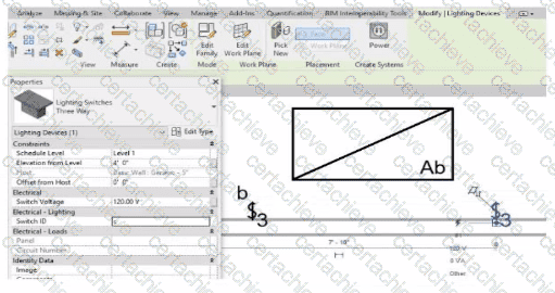
An electrical designer is trying to add the selected three-way switch to the existing switch system " b " . The designer is unable to add the switch to the switch system.
Why is this problem occurring?
Correct Answer & Rationale:
Answer: B
Explanation:
In Autodesk Revit Electrical Design , lighting control systems such as single-pole, three-way, and four-way switches are managed using Switch Systems . These systems logically connect lighting devices (switches) to the lighting fixtures they control. For multiple switches (like three-way configurations) to be part of the same control circuit, they must share the same Switch ID value.
In the exhibit, the electrical designer is attempting to add a three-way switch to the existing switch system labeled “b” , but Revit does not allow it. The reason is that the Switch ID parameter of the new switch does not match the Switch ID of the system it is intended to join.
The Switch ID acts as the unique identifier that links all switches controlling the same group of fixtures. If the IDs differ (for example, “b3” versus “b”), Revit interprets them as belonging to separate systems and prevents them from being grouped together.
The Autodesk Revit MEP User’s Guide – Electrical Systems: Lighting and Switch Systems explains this clearly:
“Switch systems are organized by Switch ID. All switches controlling the same lighting circuit must have identical Switch ID values. Revit will not allow a switch to be added to an existing system if its Switch ID does not match that system’s identifier.”
To fix this, the designer must:
1️ ⃣ Select the three-way switch.
2️ ⃣ In the Properties palette , locate the Switch ID parameter.
3️ ⃣ Change its value to match the target switch system’s ID (in this case, “b”).
Once both switches share the same Switch ID , Revit will successfully include them in the same Switch System .
Question 5
Autodesk RVT_ELEC_01101
QUESTION DESCRIPTION:
Refer to exhibit.
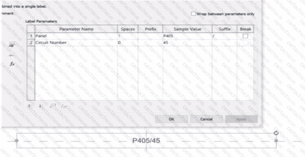
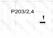
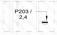
An electrical designer is working on an Electrical Device Panel-Circuit tag. The designer tags a receptacle using the tag properties shown in the exhibit The receptacle is assigned to panel P203 and circuit 2.4.
Which option shows the correct tag?
A)
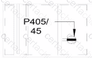
B)
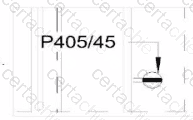
C)
D)
Correct Answer & Rationale:
Answer: B
Explanation:
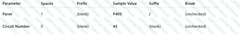
In the exhibit, the Label Parameters for the electrical device tag are configured as follows:
 A white background with black text
AI-generated content may be incorrect.
A white background with black text
AI-generated content may be incorrect.
This setup determines how the tag will display in Revit when applied to any device. Specifically:
The Panel parameter (P203 in this case) will be shown first.
A “/” separator follows because it’s assigned as the suffix for the Panel parameter.
The Circuit Number (2,4) is displayed immediately after the slash, with no extra spaces or line breaks.
Since the Break column is unchecked , the values will appear on one continuous line , not split across lines.
Revit documentation for tag creation confirms this behavior:
“When defining label parameters in a tag family, the Prefix and Suffix fields control text that appears before or after the parameter value, while the Break checkbox controls whether the text wraps to a new line.”
Therefore, when the tag is applied to a receptacle on panel P203 and circuit 2,4 , the final formatted text will be:
P203/2,4
This corresponds exactly to option B , where the panel and circuit appear on the same line separated by a slash, with no spaces or line breaks.
Question 6
Autodesk RVT_ELEC_01101
QUESTION DESCRIPTION:
Refer to exhibits.
An electrical designer models an existing receptacle on an existing wall that the architect has indicated to be demolished.
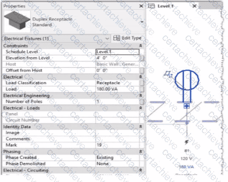
The view is intended to show demolition, and the view ' s Phase is set to New Construction. How should the designer indicate that the receptacle must also be demolished?
Correct Answer & Rationale:
Answer: C
Explanation:
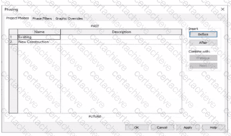
In Autodesk Revit , phasing allows designers to track existing, demolished, and new elements across different project stages. Every model element includes two key phasing parameters:
Phase Created — defines when the element was built or introduced.
Phase Demolished — defines when the element is removed or demolished.
In the provided exhibits:
The project contains two phases : Existing and New Construction.
The receptacle’s Phase Created parameter is set to Existing , indicating it belongs to the pre-existing building condition.
The architectural wall hosting the receptacle is to be demolished during New Construction .
When a view’s Phase is set to New Construction and its Phase Filter is configured to show demolition, only elements whose Phase Demolished equals New Construction will appear as to be demolished . Therefore, the electrical designer must set the receptacle’s Phase Demolished value to New Construction so that it graphically displays as a demolished element in the demolition plan.
As explained in the Autodesk Revit MEP User’s Guide – Phasing and Coordination :
“Elements created in one phase and demolished in a subsequent phase must have their ‘Phase Demolished’ parameter set to that later phase to display properly in demolition views.”
Thus, to correctly coordinate with the demolition of its host wall, the receptacle must be flagged for demolition during New Construction .
Question 7
Autodesk RVT_ELEC_01101
QUESTION DESCRIPTION:
An electrical designer needs to add spaces to a model displaying the architectural room name and number. What should the designer do before creating the spaces?
Correct Answer & Rationale:
Answer: A
Explanation:
Before placing spaces in an MEP model that should reflect architectural room names and numbers , the linked architectural model must be set to Room Bounding . This ensures that Revit recognizes the architectural walls and room boundaries, allowing the spaces to reference and display room information correctly.
As the Revit MEP documentation explains:
“Turns on the Room Bounding parameter for the linked model. This step ensures that the Revit MEP project recognizes room-bounding elements in the Revit Architecture project.”
“The spaces use the room boundaries defined by the Revit Architecture project.”
Additionally, the section Using Room Boundaries in a Linked Model details the procedure:
“In a plan view of the host project, select the linked model symbol → Click Modify | RVT Links tab ➤ Properties panel ➤ (Type Properties). In the Type Properties dialog, select Room Bounding.”
Once this setting is enabled, Revit MEP automatically detects the architectural rooms, enabling the designer to place spaces that inherit the architectural room name and number .
Question 8
Autodesk RVT_ELEC_01101
QUESTION DESCRIPTION:
An electrical designer wants to add a parameter to a lighting fixture schedule without editing the families. Which parameter type should the designer use?
Correct Answer & Rationale:
Answer: B
Explanation:
In Revit Electrical Design workflows, when a designer wishes to add a parameter to a lighting fixture schedule without editing the families themselves, the proper approach is to use a Project Parameter .
The Revit MEP documentation clearly explains:
“To add a custom field to a schedule, you can create a custom parameter using the Parameter Properties dialog. Under Parameter Type , select Project parameter .”
This method links the parameter directly to the project and to all instances of the specified category (in this case, Lighting Fixtures ), allowing it to appear in the schedule automatically without requiring any modification to the family files ( .RFA ).
In contrast:
Family Parameters apply only within the family file and are not schedulable across multiple families.
Global Parameters control dimensional or relational constraints, not schedule data.
Reporting Parameters are read-only and extract model information; they cannot be manually added to schedules.
Revit’s scheduling workflow defines this process:
“On the Fields tab of the Sheet List Properties dialog, click Add Parameter… Under Parameter Type , select Project parameter.”
This same mechanism applies to lighting fixture schedules, as schedules and sheet lists share parameter structures in Revit. The new project parameter can then be sorted, filtered, and displayed in the schedule view for documentation or tagging purposes.
[References:, Autodesk Revit MEP User’s Guide – Chapter 49 “Preparing Construction Documents,” pp. 1126–1128, Autodesk Revit Parameters Overview – “Project Parameters” and “Shared Parameters,” pp. 1541–1543, Autodesk Revit Electrical Design Essentials – Schedule and Parameter Management Section, ]
Question 9
Autodesk RVT_ELEC_01101
QUESTION DESCRIPTION:
An electrical designer wants to schedule parameters from generic annotations Which type of schedule must be created?
Correct Answer & Rationale:
Answer: C
Explanation:
When an electrical designer wants to schedule parameters from Generic Annotations , the correct method is to use a Note Block , not a generic schedule. Revit documentation defines this process clearly under Annotation Schedules (Note Blocks):
“Annotation schedules, or note blocks, list all instances of annotations that you can add using the Symbol tool.”
“Creating an Annotation Schedule (Note Block):
Load the generic annotation family or families into your project and place them where desired.
Click View tab ➤ Create panel ➤ Schedules drop-down ➤ Note Block.
In the New Note Block dialog, for Family, select a generic annotation. ”
This extract confirms that when working with generic annotation families , Revit requires the use of a Note Block to extract and list their parameters in a schedule. Standard schedules such as Generic Model or Family schedules cannot access data from Generic Annotations since they are annotation-based, not model-based.
Question 10
Autodesk RVT_ELEC_01101
QUESTION DESCRIPTION:
When creating a power circuit, which two rules are enforced by the program? (Select two.)
Correct Answer & Rationale:
Answer: A, C
Explanation:
According to the Autodesk Revit MEP User’s Guide (Chapter 17 – Electrical Systems), when creating power and lighting circuits, Revit enforces specific compatibility rules to ensure the accuracy and integrity of electrical systems. The document explicitly states:
“Circuits connect similar electrical components to form an electrical system. Once created, you can edit circuits to add or remove components, connect a circuit to a panel, add wiring runs, and view circuit and panel properties… A component can be connected in a circuit if it is compatible with the other components in the circuit and if it has an available connector.”
Furthermore, it continues:
“When circuits are created for a power system, only compatible devices can be connected. All devices in a circuit must specify the same distribution system (voltage and number of poles). The distribution system can be specified by type parameters or instance parameters. When you create a circuit where all the devices have the distribution system specified as instance parameters, Revit MEP displays a Specify Circuit Information dialog where you can specify values for the number of poles and voltage prior to creating the circuit.”
Additionally, the documentation clarifies that circuits must exist within the same project model to maintain system logic and consistency. It explains that “circuits connect similar electrical components within a particular system ,” which implicitly enforces that items must reside in the same model file. Revit’s data structure does not allow cross-model circuit connections, since circuit logic, load calculations, and panel assignments depend on shared model parameters and hosted relationships between electrical families.
Therefore, the two rules enforced by Revit when creating a power circuit are:
A. Items on the circuit must be in the same model. This ensures data integrity and consistency across electrical systems, as circuits cannot span multiple linked models.
C. Items on the circuit must be assigned the same voltage definition. This guarantees that only devices with matching voltage and pole configurations can be logically and electrically connected to the same circuit.
Other options, such as requiring apparent load values or association with transformers, are not mandatory for circuit creation—they are design considerations applied after circuits are established. Worksets (option D) manage collaboration, not circuit validity.
Verified Reference:
Autodesk Revit MEP 2011 User’s Guide, Chapter 17 “Electrical Systems,” Sections Creating Circuits and Creating Power and Lighting Circuits , pp. 461–463.

Verified by Certified Instructors
This Autodesk RVT_ELEC_01101 study pack was audited and verified on June 25, 2026 by Elon Ashford,. We ensure every technical rationale aligns with real-world enterprise standards.
A Stepping Stone for Enhanced Career Opportunities
Your profile having Autodesk Certified Professional certification significantly enhances your credibility and marketability in all corners of the world. The best part is that your formal recognition pays you in terms of tangible career advancement. It helps you perform your desired job roles accompanied by a substantial increase in your regular income. Beyond the resume, your expertise imparts you confidence to act as a dependable professional to solve real-world business challenges.
Your success in Autodesk RVT_ELEC_01101 certification exam makes your visible and relevant in the fast-evolving tech landscape. It proves a lifelong investment in your career that give you not only a competitive advantage over your non-certified peers but also makes you eligible for a further relevant exams in your domain.
What You Need to Ace Autodesk Exam RVT_ELEC_01101
Achieving success in the RVT_ELEC_01101 Autodesk exam requires a blending of clear understanding of all the exam topics, practical skills, and practice of the actual format. There's no room for cramming information, memorizing facts or dependence on a few significant exam topics. It means your readiness for exam needs you develop a comprehensive grasp on the syllabus that includes theoretical as well as practical command.
Here is a comprehensive strategy layout to secure peak performance in RVT_ELEC_01101 certification exam:
- Develop a rock-solid theoretical clarity of the exam topics
- Begin with easier and more familiar topics of the exam syllabus
- Make sure your command on the fundamental concepts
- Focus your attention to understand why that matters
- Ensure hands-on practice as the exam tests your ability to apply knowledge
- Develop a study routine managing time because it can be a major time-sink if you are slow
- Find out a comprehensive and streamlined study resource for your help
Ensuring Outstanding Results in Exam RVT_ELEC_01101!
In the backdrop of the above prep strategy for RVT_ELEC_01101 Autodesk exam, your primary need is to find out a comprehensive study resource. It could otherwise be a daunting task to achieve exam success. The most important factor that must be kep in mind is make sure your reliance on a one particular resource instead of depending on multiple sources. It should be an all-inclusive resource that ensures conceptual explanations, hands-on practical exercises, and realistic assessment tools.
Certachieve: A Reliable All-inclusive Study Resource
Certachieve offers multiple study tools to do thorough and rewarding RVT_ELEC_01101 exam prep. Here's an overview of Certachieve's toolkit:
Autodesk RVT_ELEC_01101 PDF Study Guide
This premium guide contains a number of Autodesk RVT_ELEC_01101 exam questions and answers that give you a full coverage of the exam syllabus in easy language. The information provided efficiently guides the candidate's focus to the most critical topics. The supportive explanations and examples build both the knowledge and the practical confidence of the exam candidates required to confidently pass the exam. The demo of Autodesk RVT_ELEC_01101 study guide pdf free download is also available to examine the contents and quality of the study material.
Autodesk RVT_ELEC_01101 Practice Exams
Practicing the exam RVT_ELEC_01101 questions is one of the essential requirements of your exam preparation. To help you with this important task, Certachieve introduces Autodesk RVT_ELEC_01101 Testing Engine to simulate multiple real exam-like tests. They are of enormous value for developing your grasp and understanding your strengths and weaknesses in exam preparation and make up deficiencies in time.
These comprehensive materials are engineered to streamline your preparation process, providing a direct and efficient path to mastering the exam's requirements.
Autodesk RVT_ELEC_01101 exam dumps
These realistic dumps include the most significant questions that may be the part of your upcoming exam. Learning RVT_ELEC_01101 exam dumps can increase not only your chances of success but can also award you an outstanding score.
Top Exams & Certification Providers
New & Trending
- New Released Exams
- Related Exam
- Hot Vendor